
7 layers of networking (OSI model) sections:
- Physical layer
- Data link layer
- Network layer
- Transport layer
- Session layer
- Presentation layer
- Application layer
If you are a sane person you are most probably wondering what a plumber has to do with 7 layers of networking? Here comes the answer.
The other day I had a clogged toilet and needed a plumber asap because…. Well, you can imagine… I immediately called a local plumbing provider and they sent their best plumber on duty – Mr. Ivo.

Ivo is a 54-year-old male with the white beard and a smile in his eyes that good people have. He is very curious to know everything and he is not hiding that desire in his questions.
Ivo saved my toilet in minutes and then went on explaining to me all the secrets of plumbing (even though I did not insist to know).
As I was getting to know all the plumbing nitty-gritty, this conversation has become increasingly pleasant since it is always nice to listen to someone who speaks with such enthusiasm as Ivo spoke of toilets! For instance, toilet brushes he considers the most important objects in one’s household!

When Ivo found out that I am an engineer, he wanted to know all about how computers work and communicate. Soon after, I found myself explaining 7 layers of networking to my plumber Ivo!
I decided to publish this conversation but without Ivo’s side since he kept exclaiming sentences such as “holly f***” during many of his Aha moments!
Because of its potential use to Ivo and to all of you, I explained the 7 layers of networking in a way that everyone understands! So, keep reading it even if you are not a plumber!
Now, prior to digging into the first layer called the Physical layer, let’s spend a few lines on the OSI model.

The OSI model
Before throwing some definitions at you, I am going to explain the gist of the model by using a practical example. Imagine that you have an old-school mobile phone with buttons to accept and deny calls as below.

Now also imagine that you give that phone to your grandmother who is 90 years old with the instruction to press the green button when the mobile rings.
Pressing the green button is an instruction that is sufficient for the two mobiles to connect. Your grandmother needs not to know anything about the mobile maker, the installed hardware, or the operating system as long as she follows the instructions. (Call your grandmother sometimes if she is still around, time passes by quickly!)
Minding this analogy, the open system interconnection (OSI) model is not as cool as its name suggests. It is actually much simpler than it sounds. In short, the model gives guidance on how interconnected devices (e.g. computers) talk to each other WITHOUT specifying the underlying technology of each.
So, for the OSI model, it doesn’t matter who the manufacturer of a computer is, what OS the computer runs on, or any other individual characteristic. Not even if a device is a computer or a coffee machine. It only matters that the device has pieces of hardware where certain standard protocols are installed (e.g. IP/TCP, HTTP). The devices that have these standard protocols can then communicate seamlessly.
💡TechTarget’s definition of a protocol:
A network protocol is a set of established rules that dictate how to format, transmit and receive data so that computer network devices — from servers and routers to endpoints — can communicate, regardless of the differences in their underlying infrastructures, designs or standards.
TechTarget
Yeaaaahhhh! Now you know what plumbing has to do with the OSI model and much more actually.
You also know that the model is used to describe procedures that computers follow (or other devices) in order to talk to each other. Now, why should you bother reading further about the layers?
Well, after you understand the layers you will be able to troubleshoot connection problems in real-world projects much easier and with rock-solid confidence — you will know where to look at!
Without further ado, let’s explain the 7 layers that the OSI model consists of.
Layer 1: Physical layer
This one is simple – just look at the name — physical layer! Layer 1 is therefore responsible for a physical connection between the devices that talk to each other. Physical connection means that you can track the cable from one device to another!
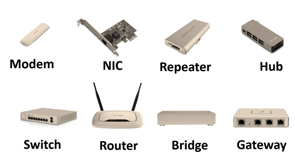
The infrastructure that supports layer 1 involves cables (e.g. Ethernet/LAN cable), hubs, repeaters, and modems.
Since computers exchange the raw data in bits (sets of zeros and ones), the physical layer must translate these bits into electrical signals (of a given voltage). This is because only electrical signals CAN travel through the cables (physical media).
Another important agreement at the layer 1 level is the rate of bits per second sent from the sender to the receiver. That is the pace of transferring the raw data from one device to another (transmission rate).

Now, what benefits do you get from understanding the physical layer? Well, if your laptop or server is not reachable from another device, the first on the checklist are the cables and the related infrastructure (hub, modem).
It can well be that you have got a little friend that feeds on some of your layer 1 infrastructures.

Or someone has just poured water into the hub as if it was a plant.
Layer 2: Data link layer
The data link layer is responsible for communication between the nodes that belong to the same network (e.g. LAN). The main task of Layer 2 (L2) is to organize bits of the raw data into FRAMES and make sure that these get delivered from the sender to the receiver. Of course, the delivery goes through the wires of the physical layer (L1).
Frames
Now, do not panic — let me explain what a frame is. A frame is nothing else but a vehicle by which the data travels through the local network.
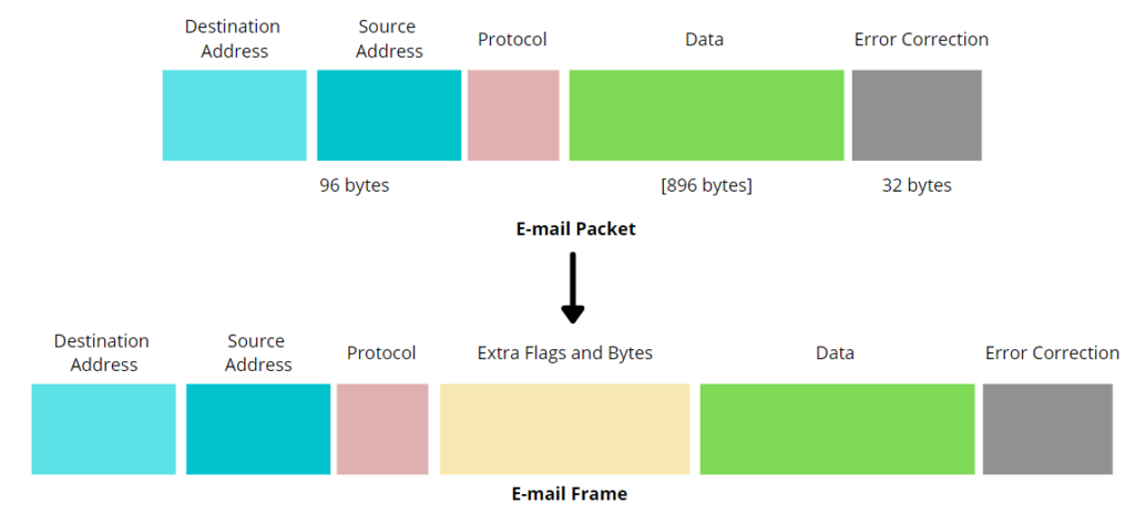
L2 is splitting the raw data into manageable chunks of bits that are sent (streamed) further via frames. Every frame contains the header section which refers to the sender’s and the receiver’s address and the body that holds the bit representation of the raw data. Here is the detailed structure of a frame.
MAC address
The source and destination address here is referenced as MAC (Media Access Control) address. The MAC address is a unique address that is used to identify devices in the local network. It is assigned by the device’s manufacturer and its main purpose is to identify the sender and the recipient of the data traveling through L1. Because of this, the MAC address is also called a permanent and physical address (usually printed on a sticker on the backside of a device).
💡Do not confuse IP address for MAC address. MAC address is used in local networks and it is locally unique. An IP address is used to access the internet and it identifies a device globally making it unique on the internet.
Common pieces of hardware that support the data link layer include NIC cards (Network Interface Card), switches, and bridges. A common L2 protocol that uses these devices is the Ethernet protocol (LAN). Because of that, we can say that L2 consists of hardware parts AND protocol(s).
Error handling
If you are on the earth long enough, you most probably know that s*** happens all the time. The same applies to our L2 layer.
Bits that are traveling through the local network wires (L1) can get corrupt. This means that what was sent by the sender differs from what the recipient has received. If an alike situation happens, the problematic frame is sent again (retransmitted) until the recipient acknowledges that the bits completely match the expected.
You do not want your cat’s photo to get corrupt and to look like the one here. That’s why L2 has its error handling capabilities. These make sure that what you expect is what you get!

You probably understand now that the less sophisticated communication is, the fewer layers get involved. Also, the smaller the scope, the fewer layers – e.g. the local networks need only the first and the second layer in order to work.
Get ready for the real thing now! With the next layer, we are going to the public network (the internet)! There is a common saying in Serbia – do you want to be the best in your village or mediocre in a city? Let’s not be satisfied with being the best in the village, that is, with knowing only about the local networks!
Layer 3: Network layer
The network layer allows the nodes (servers) that belong to different networks to exchange the data. Until this moment, we have talked about local networks where computers communicate via L1 and L2. The network layer (L3 ) brings a new functionality by enabling the communication of the nodes that belong to completely different local networks.
A Global (public) network of computers (the Internet) makes this communication possible! Before you continue further, read what the internet is and understand IP address basics.

Packets
Geeks call the data unit that travels through the L3 a packet. Since you already understand what a frame is, you can use similar reasoning to understand a packet. The catch is that the data traveling through different layers, get different names but the concept remains the same – data in transit.
A packet contains sender and receiver addresses, protocols to be used (e.g. IP protocol), the raw data representation, and the error control chunk.
💡You can understand the difference between a frame and a packet from the graph below (graph by Baeldung.Com).
Logical addressing
If your memory is better than in a golden fish (around 3 secs), you can recall that L2 uses MAC addresses to understand who the sender and the receiver is. We called this concept the physical address since the MAC address is permanently written on the device itself.
As opposed to L2, L3 uses a concept of logical addressing to trace who the sender and the receiver is. You can compare this to your fixed telephone line – your phone number is not written on the backside sticker of the device itself. Hence, we can say that the telephone number also follows the logical addressing.
In a similar way, every device connected to the Internet has a logical (public) IP address that is unique across the globe. A packet contains exactly these and L3 uses the IP address of the sender and receiver to successfully deliver the packet from A to B.

Routing
The main device of the network layer is called the router. The router is also built into your modem and its main purpose is the packet forwarding (routing) service.
By looking at the receiver’s IP address from a packet, the router forwards the packet to the next node in the network that is one step closer to the destination node (recipient).
During the routing process, the packet is traveling (hooping) through the network of interconnected computers until finally reaches the destination. This step-by-step approach is possible thanks to routing tables that I will explain in another post.
That’s how you can send your holiday photos to your friends. Even though people usually do not like getting too many of other people’s holiday photos.

Before moving on, it is important that you understand that the layers work together rather than in isolation. That means that once the packet reaches its destination’s L3, gets delegated to L2 which sends the packet’s content over L1 to the recipient from its local network!
Layer 4: Transport layer
The transport layer consists of protocols — TCP and UDP (both built on top of the IP protocol). You can think of these protocols as a software peace (driver) that is installed on the machine participating in the data exchange.
The transport layer (L4) is a man in the middle between the client (application the user interacts with) and the wider network of computers that receive the client-generated data.
This man-in-the-middle role is similar to the role of pub bouncers. Now, what is that the bouncers usually do — except occasionally punch you in the face (we have all been there)?
The bouncers organize the queue in two people per line formation, let more people into the pub (when the waitress calls for it), kick the trouble-making drunk out (do not let the too drunk enter the pub), and scan if your outfit is suitable for this pub…

L4 role at sender’s machine
Similar to the bouncer, L4 takes the data from the upper (application) layers and organizes (classifies) the data into so call segments.
Segments are the core data units traveling through L4. Similar to the other data units (frames, packets), these contain the application data (e.g. a Whatsup text message) and some L4-specifics such as source port and destination port (in the header section). An example of a segment’s header is below (the body contains the actual data).
1. Sender Port
2. Receiver Port
3. Flag bits
4. Sequence Number of the Segments
5. Checksum
6. Options Field
💡Segments contain the sender’s and receiver’s ports since all the applications are running within a certain port of a given host. Notice that the host part is redundant here since L3 is in charge of this part and not L4! L4 is therefore a glue that ensures process-to-process delivery of error-free data!
Once L4 has finished with the segmentation, the segments are pushed to L3 where these get enriched further and reorganized in packets before L3 sends them to the next layer.
L4 role at receiver’s machine
After the receiver gets the data, L4 is in charge of taking the packet from L3, making sure it is error-free and safe to hand it over to the application layers.
In other words, L4 is handling a typical assembly/reassembly task by mediating between L3 and L5-L7. Crucial here to understand is that L4 is delivering to a certain port — that is, to an app running on a given port!
Flow control and error handling
As we mentioned in the beginning, L4 consists of two main protocols — TCP and UDP protocol. These are alternatives to one another (if you use UDP you are not using TCP). That said, there are also use cases where you would prefer UDP to TCP. To understand the error handling better and the flow control capabilities of L4, I am going to explain a bit about each of the two.
TCP (Transmission Control Protocol)
TCP protocol assumes a two-way connection between the devices so that each can transfer the data to the other side. This connection establishment lasts sometime before the parties are ready to send/receive the data. Also, the connection should be aborted at the end of the transfer. Due to this, the TCP protocol involves connection management overhead that costs time and resources.
As all in life, costs come with benefits. TCP is able to track the sequence of packets being sent and resend a given packet should the packet gets lost. In other words, the TCP connection allows for the receiver to acknowledge that the packet has been orderly received. If the sender does not receive this acknowledgment, the sender will simply send the packet over again. That said, TCP can guarantee data delivery! How cool is that?

Due to its warranty-like features, TCP contains a solid error-checking mechanism so that it knows which packets arrive incomplete or do not arrive at all. These error handling capabilities demand additional entries in the TCP header section compared to the UDP headers.
TCP is suitable for data transfer where you cannot afford to lose any packet since you would not understand the data. For instance, sending a photo of your cat — should the packet gets lost (and not reissued) the photo would be corrupted and fail to open. The same for your email — you do not want half of your email in characters like these!

Because of these reasons, the HTTPS and the SMTP protocol both use TCP as a base. HTTPS you use to browse the web and SMTP to send emails!
UDP (User Datagram Protocol)
It is easy to understand UDP if you understood TCP. UDP is simply what TCP is not!
UDP is a fire and forget mechanism which means that there is no acknowledgment of the received packets. The sender simply works on the best-efforts basis. In the case of lost or incomplete packets, the receiver is responsible to ask again for the transfer.
That said, UDP is not able to reissue the lost packet nor track the packet sequence. Also, it contains only a basic error check in form of checksums which makes it less reliable than TCP.
The plus side of UDP is that it does not have connection management overhead since it is a one-way street. The sender is blindly sending data and it is completely up to the receiver to complain if something is not received. This makes UDP incredibly fast (faster than TCP)!
I hope that you get this joke, else I failed to explain L4 protocols. Write in a comment if you got it! 💬

Based on the above, UDP is suitable for video streaming platforms and other use cases where speed matters and where the receiver can easily ask for lost packet transmission!
That is it for the transport layer, you completed layer 4!
The coming layers (layer 5, layer 6, and layer 7) all belong to the application-side layers. We are therefore switching to the application supporting layers where the application is a piece of software the user interacts with (e.g. a browser or an email client).
Layer 5: Session layer
Wikipedia defines a session as this.
In computer science and networking in particular, a session is a time-delimited two-way link, a practical (relatively high) layer in the tcp/ip protocol enabling interactive expression and information exchange between two or more communication devices or ends – be they computers, automated systems, or live active users (see login session)
Wikipedia
The gist of this definition is that sessions are based on the TCP/IP protocol (L4) and as such enables two (or more) devices to establish a two-way link for exchanging data! So, before the data transfer begins, we must have an active session!
L5 is responsible for initiating a connection between your computer and a distant server. L5 also takes care of user and password validation (authentication), connection maintenance, and ultimately connection termination.
💡Data unit of this layer (and L6 and L7) is called a message.
Also, the session layer regulates the communication peace between the connected computers by introducing synchronization checkpoints. This means that if some of the streamed data gets lost in the transfer, the retransmission starts right from the point of the lost data (not for the entire data set).

In short, L5 is a bridge between an application you are running and a server that delivers the data to you over the network. L5, therefore, takes on data from the transport layer (L4) and forwards it further to the presentation layer (L6) and vice-versa. All the tasks that relate to establishing and maintaining a two-way link for data transfer fall under the scope of the session layer!
Layer 6: Presentation layer
To give you a hint of what this layer does, I can tell you that some people recognize L6 by a different name — The translation layer!
Similar to human translators, L6 translates data that is coming from L5 so that the next layer (application) can understand the format and present the data to the final user.
In the other direction, the same applies – L6 is translating data coming from L7 so that L5/L4 can understand it.
L6 is basically a network translator that handles two main functions – data formatting and data compression.

For data to travel the network, it must be in a certain format. Applications usually receive text input from the users and L6 is responsible to format the input further. The transport layer also standardizes the syntax of different data types traveling the network (so that every application can understand the data).
In some cases, the client application is using a secure connection (HTTPS). L6 is then encrypting the data — makes it appear random — before sending it further. At the receiver end, the presentation layer is decrypting the data — making it readable again — so that the user sees the right data in the app!

Another job that L6 does is the serialization of the data. This process is important because the user can supply different data types (text, images, videos). It is therefore L6’s task to (serialize) make this input as light to store/transfer as possible.
Also, depending on the compression settings, the transport layer reduces the size of the raw data by compressing it! Once L6 compresses the data, it is faster and more efficient to send the data over the network (less bandwidth).
You have just read the final sentence of the presentation layer!
Layer 7: Application layer
Here it all comes together! Consider this photo.
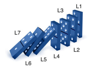
The user sees the application layer (L7). This is a piece of software the user is interacting with (an email client or a web browser). Once the user clicks the send button (for the email) or hits the enter button (in the browser), the domino effect starts! Just like dominos, the message is traveling through all the layers before being visible at the destination computer.
Now that you understand the big picture, I want to be a bit more specific. The application layer is made of protocols that web browsers and email clients have under the hood. So, L7 is not Mozilla Firefox but rather a protocol that Mozilla Firefox speaks (HTTP). Outlook is not L7 but embodies L7 through SMTP (Smart Email Transfer Protocol)!
Some other popular application layer protocols include FTP (File Transfer Protocol), POP (Post Office Protocol), and SSH (Secure Shell Protocol).
L7 is therefore using a given software to display the data to the final user! And now, you know that the data is coming from a distant server through L1, L2, L3, L4, L5, and L6 before it hits L7!
Some Final Words
With this kilometers-long post, you started building a solid foundation of computer network knowledge. If you have come so far, you are one of us!
You now know that users produce the data in L7. This data gets further pushed down the stack (L6, L5…) till it hits L1. At L1, data travels in the form of bits to the destination where the fun starts again!
Once at the destination, the data is climbing the layers (L2, …, L6) until it is finally visible to the user at L7!
And that’s it, no b******* talks with you on the computer networking layers subject — you know the thing!
P.S. If you find this post useful, you might want to read my other post: Python Beginners Guide: The way rich kids are taught [2022]. Also, it is very logical that you read this post on DNS in computer networks as a next step.

 job")


2 replies on “7 layers of networking explained to a plumber [True Beginner’s Guide]24 min read”
This is well explained, I can apply it when troubleshooting the networking issues at work
mumu